GRILLE-PAIN DE CONTACT VERTICAL
POWER
CORD
TERMINAL
BLOCK
GRN
GND
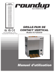
DIAGRAMME DE CÂBLAGE
Diagramme de câblage du VCT-20
WIRING DIAGRAM
NOTE: ALL WIRES TO BE 14 GA. AWM-105°C
UNLESS OTHERWISE SPECIFIED.
* 16 GA. TFE-200°C
= 18 GA. AWM-105°C
# 16 GA. AWM-105°C
% 14 GA. TFE-200°C
HI-LIMIT
THERMOSTAT
*WHT
WHT %WHT
% WHT
% WHT
POWER
SWITCH
1 2
= WHT
4 5
INDICATOR
LIGHT
M
MOTOR
*BLK
THERMOSTAT
% BLK
% BLK
% BLK
INTERLOCK
SWITCH
% BLK
Diagramme de câblage du VCT-25 et du VCT-50
POWER
CORD
WIRING DIAGRAM
NOTE: ALL WIRES TO BE 14 GA. AWM-105°C
UNLESS OTHERWISE SPECIFIED.
* 16 GA. TFE-200°C
= 18 GA. AWM-105°C
# 16 GA. AWM-105°C
% 14 GA. TFE-200°C
TERMINAL
BLOCK
GRN
GND
HI-LIMIT
THERMOSTAT
*WHT
*WHT
50HZ
WHT
%WHT
POWER
SWITCH
1 2
4 5
= WHT
INDICATOR
LIGHT
M
COM
THERMOSTAT
% BLK
% BLK
INTERLOCK
SWITCH
% BLK
P/N 1010729FRA Rev. C 09/12
Transcribed 1010729 Rev. F 09/12
19