Allen-Bradley Iso Busbar Modules Guide d'installation
Vous trouverez ci-dessous de brèves informations pour Iso Gerätemodule. Ce manuel fournit des instructions détaillées sur l'assemblage et le démontage des modules, l'installation de l'adaptateur, et la position de test. Suivez ces instructions pour installer et entretenir correctement vos modules.
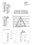
Fonctionnalités clés
Assemblage facile des composants
Instructions de montage de l'adaptateur
Procédure de position de test
Démontage sécurisé de la plaque d'adaptation
Reconnexion correcte de la plaque d'adaptation
Foire aux questions
Pour éviter les chocs électriques, coupez l'alimentation avant d'installer ou d'effectuer des réparations. Installez dans un boîtier approprié et protégez contre les contaminants.
La mise en service et la maintenance doivent être effectuées uniquement par du personnel qualifié.
Oui, la section 2 explique comment assembler les composants avec des diagrammes.
Oui, la section 6 explique comment démonter la plaque d'adaptation de l'appareil.
Associés

Abdeckhaube | Chat IA et téléchargement PDF

KHW EEC6025-L+: Chat IA et téléchargement PDF

60mm-System Compact : Chat IA et Téléchargement PDF

Classe J : Chat IA et téléchargement PDF
Manuel d'utilisation QUADRON 185POWER

QUADRON®185Power Taille 00 : Chat IA et PDF

QUADRON®185Power Größe 1-2-3 : Chat IA et PDF
QUADRON®185Power Größe 1-2-3 | AI Chat & PDF
