Allen-Bradley 100C,C09S..C23S, CONTACTOR/RELAY Guide d'installation
Vous trouverez ci-dessous de brèves informations pour -CF...S / CS...S, -C09S / ...-9S, -C12S / ...-12S, -C16S / ...-16S, -C23S / ...-23S. Il est important de déconnecter l'alimentation avant l'installation ou la maintenance pour éviter tout choc électrique. Ces dispositifs doivent être installés dans un boîtier approprié dans les environnements à risque de contamination ou d'émissions agressives et ne doivent pas être actionnés manuellement. Respecter les distances minimales par rapport aux pièces mises à la terre.
Fonctionnalités clés
Nécessite un boîtier approprié dans les environnements contaminés.
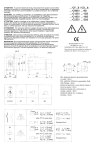
Bornes pour conducteurs en cuivre de 75°C uniquement.
Couple de serrage spécifié pour les bornes.
Distances minimales à respecter pour l'installation.
Foire aux questions
Déconnecter l'alimentation électrique pour éviter les chocs électriques.
Dans les environnements présentant un risque de contamination ou des émissions agressives.
Ne pas actionner manuellement.
6 mm
Associés

Alpha Lovag CF...Y, CS...D Instructions + Chat IA

Manuel Q7-16C, Q-C16Z Allen-Bradley | IA et PDF

C30Y, 30-D, C37Y, 37-D: Manuel d'instructions + IA

193-E, CEP7 : Chat IA et téléchargement PDF

Manuel de démarrage rapide 100L-C20 Allen-Bradley

S-C43Z(D) et S7-43C(D) : Manuel et Chat IA

S-C43 Contactors : Chat IA et téléchargement PDF

Manuels S-C30Z(D), S7-30C(D) | Chat IA & PDF

-PA... Instructions + Chat IA et téléchargement PDF

CF...S, CS...S Contacteurs Manuel | AI Chat & PDF

C30S, 30S, C37S, 37S : Instructions + Chat IA
