RE
1001
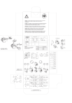
Attention: To prevent electrical shock, disconnect from power source before
installing or servicing. Install in suitable enclosure. Keep free from
contaminants.
Achtung: Vor Installations- oder Servicearbeiten Stromversorgung unterbrechen,
um Unfälle zu vermeiden. Die Geräte müssen in einem passenden Gehäuse
eingebaut und gegen Verschmutzung geschützt werden.
Attenzione: Per prevenire infortuni, togliere tensione prima dell’installazione
o manutenzione. Installare in custodia idonea. Tenere lontano da contaminanti.
Attention: Avant le montage et la mise en service, couper l’alimentation
secteurafin d'éviter tout accident. Prévoir une mise en coffret ou armoire
appropriée. Protéger le produit contre les environnements agressifs.
Atención: Desconectar la alimentación eléctrica antes de realizar el montaje
y lapuesta en servicio, con el objeto de evitar accidentes. Instalado en una
caja o armario apropiado. Proteger el producto de los ambientes agresivos.
gG
max.
Type 1
Type 2
30
37
43
125 A
125 A
160 A
80 A
80 A
100 A
IEC 60947-5-1
EN 60947-5-1
gG
max.
-CR...
-FS...
-PV...
-FA...
-FB...
-FC...
Tech.
Data
10 A
Circuit Breaker
600 Volts Maximum
125 A
125 A
125 A
25°
c
53
103
106
54
63
30
37
43
c1
c
a
[mm]
2
1
8
4
10
6
12
5
9
3
11
30/37
43
1 x 2.5...10 mm2
2 x 2.5...10 mm2
No. 14...6 AWG
1 x 2.5...16 mm2
2 x 2.5...10 mm2
No. 14...6 AWG
Use 75°C Cu wire only
1 x 2.5...16 mm2
2 x 2.5...16 mm2
No. 14...6 AWG
Use 75°C Cu wire only
1 x 2.5...25 mm2
2 x 2.5...16 mm2
No. 14...6 AWG
1 x 1...2.5 mm2
2 x 1...2.5 mm2
No. 16...12 AWG
1 x 1...2.5 mm2
2 x 1...2.5 mm2
No. 16...12 AWG
Use 75°C Cu wire only
1 x 1...4 mm2
2 x 1...4 mm2
No. 16...12 AWG
Use 75°C Cu wire only
1 x 1...4 mm2
2 x 1...4 mm2
No. 16...12 AWG
30/37
DC
max. 4 N.C.
11 mm
+
max. 2 N.O.
A1
A2
9 mm
53
11
5°
c+
7
IEC 60947-1/-4-1/-5-1
EN 60947-1/-4-1/-5-1
UL 508; CSA 22.2 Teil 14;
34
c1
a
34
d
d
9
c+
60
81
105
5°
11
11
5°
[mm]
56
ø 4,5
-CV...
-FL...
Schachtel 22.221.861-01
Druckvorlage 22.037.416 / 6. 2003 / Ausg.3
1.5...3.5 Nm
13...31 lb-in
No 3
Pozidriv No 2
1...1.5 Nm
8.9...13 lb-in
No 3
Pozidriv No 2
35
For 100-C43Y* + 193-E...D
change adapter on 193-E...D
Size Fuse
600 Volts Maximum
30 110 A
37 125 A
43 150 A
56
USA/CND
Suitable for use on a circuit capable of
delivering not more than 5000 rms
symmetrical amperes
-PV...
-FA...
-FB...
-FC...
-PA...
-SA...
-SB...
45
2
max.
Type 2
98
1
101
IEC 60947-4-1
EN 60947-4-1
Ue ≤ 690 V
-CZ...
-FPT...
">